| Sign In | Join Free | My futurenowinc.com |
|
| Sign In | Join Free | My futurenowinc.com |
|
| Categories | 5G Network Equipment |
|---|---|
| Brand Name: | ZTE |
| Model Number: | ZXDU58 W121 |
| Certification: | CE, RoHS |
| Place of Origin: | China |
| MOQ: | 1 set |
| Price: | negotiable |
| Payment Terms: | L/C, T/T |
| Supply Ability: | 1000 sets/month |
| Delivery Time: | within 10 days of payment |
| Packaging Details: | carton box |
| Output Voltage: | -53.5 V DC |
| Phase Voltage: | 220 V - 240 V |
| Line Vlotage: | 380 V - 415 V |
| Input Frequency: | 50 Hz / 60 Hz |
| AC Input: | Three-phase five-wire |
| Rectifier: | Four ZXD1500 rectifiers |
ZXDU58 W121 V4.0R01M08 ZTE Outdoor DC Power System For Communications Equipment
System introduction
The ZXDU58 W121 system is an outdoor DC power. It provides -53.5 V
DC power for communications equipment.
AC input mode: Three-phase five-wire (L1/L2/L3/N/PE), 220 V - 240 V
(phase voltage) / 380 V - 415 V (line voltage), 50 Hz / 60 Hz.
In full configuration, the ZXDU58 W121 system is equipped with four
ZXD1500 rectifiers, which form a rated output current of 120 A.
For the ZXDU58 W121 system appearance, see Figure 1-1.

System features
The ZXDU58 W121 system has the following features:
*A wide range of input phase voltage (80 VAC - 300 VAC) makes the
system suitable for areas with unstable voltage.
*Integrating the power distribution, rectifiers, CSU and batteries
in a single cabinet, and thus saving installation space.
*The rectifier is hot-pluggable, and convenient for installation
and maintenance.
*Intelligent CSU.
*With heat exchanger and Thermoelectric Cooler (TEC) for heat
dissipation.
*High reliability with Mean Time Between Failures (MTBF) ≥ 2.2 ×
105 h.
*Multiple networking interfaces: input relays, output relays, RS232
interfaces, and RS485 interface.

| Item | Description |
| Cabinet dimensions (H × W × D) | Without thermoelectric cooler: 2200 mm × 700 mm × 700 mm With thermoelectric cooler: 2200 mm × 700 mm × 850 mm |
| Communications equipment space | 19 inches in width, 14U in height (1U = 44.45 mm) |
| Battery space (H × W × D) | Two battery racks Each rack provides a net installation space of 335 mm × 537 mm × 552 mm. |
| Dimension of the floor-mounting holes | 8–Ø16 mm |
Internal Structure
The internal space of the ZXDU58 W121 cabinet is divided into the
equipment space and the battery space.
For the internal structure, see
For a description of the components, refer to Figure 2-2.

1. Heat exchanger
2. Thermoelectric cooler
3. Heater for battery space (optional)
4. Battery space
5. Power supply chassis
6. Signal Interface Board (SIB)
7. Communications equipment space
8. Ventilation subrack
9. Emergency light (optional)
10. Smoke sensor (optional)
11. Fan control board (FCTL)
12. PE busbar
13. Relay board (RLY)
14. Environment Monitoring Board (EMB)
15. Heater for equipment space (optional)
16. Internal cabling holes
17. External cabling holes
18. Door sensor
19. GND terminals
Table 2-2 Component Description
| S.N. | Component | Description |
| 1 | Heat exchanger | For heat dissipation of the equipment space |
| 2 | Thermoelectric cooler | For heat dissipation of the battery space |
| 3 | Heater for battery space | Optional, to heat the battery space if needed |
| 4 | Battery space | Two battery racks. Each rack provides a net installation space of 335 mm × 537 mm × 552 mm (H × W × D) |
| S.N. | Component | Description |
| 5 | Power supply chassis | Provides power input/output distribution and converts AC to DC For the further details, refer to 2.3 Power Supply Chassis. |
| 6 | Signal Interface Board (SIB) | Provides background communication interfaces and supervision
interfaces For the further details, refer to 2.6.1 Interface of SIB Board. |
| 7 | Communications equipment space | Installs the communications equipment. 19 inches in width, and 14 U in height |
| 8 | Ventilation subrack | For internal air circulation of the equipment space |
| 9 | Emergency light | Optional, for emergency lighting |
| 10 | Smoke sensor | Optional, for smoke detection |
| 11 | Fan control board (FCTL) | Controls the operation of the fans in the heat exchanger and the ventilation subrack |
| 12 | PE busbar | - |
| 13 | Relay board (RLY) | Provides eight output relaysFor the further details, refer to 2.6.2 Interface of RLY Board. |
| 14 | Environment Monitoring Board (EMB) | Provides environment monitoring interfacesFor the further details, refer to 2.6.3 Interface of EMB Board. |
| 15 | Heater for equipment space | OptionalHeats the power & communications equipment space if needed |
| 16 | Internal cabling holes | - |
| 17 | External cabling holes | - |
| 18 | Door sensor | For door status detection |
| 19 | GND terminals | - |
Power Supply Chassis
The power supply chassis provides power input/output distribution
and converts AC to DC. For the layout of the components of the
power supply chassis.

1. AC input circuit breaker
2. AC auxiliary output circuit breaker
3. AC SPD
4. DC output circuit breakers ( LLVD1)
5. DC output circuit breakers (LLVD2)
6. Battery input circuit breakers
7. DC Surge Protection Device (DC SPD)
8. Centralized Supervision Unit (CSU)
9. ZXD1500 rectifiers
For the internal structure of the power input/output distribution part

For a description of the components
| S.N. | Component | Description |
| 1 | AC input circuit breaker | Activates/deactivates AC input branch |
| 2 | AC auxiliary output circuit breaker | Activates/deactivates AC auxiliary input branch Reserved for the heaters for the equipment space and the battery space |
| 3 | AC SPD | Provides AC input surge protection |
| 4 | DC output circuit breakers ( LLVD1) | Activate/deactivate DC output (LLVD1) branches |
| 5 | DC output circuit breakers (LLVD2) | Activate/deactivate DC output (LLVD2) branches |
| 6 | Battery input circuit breakers | Activate/deactivate battery input branches |
| 7 | DC Surge Protection Device (DC SPD) | Provides DC output surge protection |
| 8 | Centralized Supervision Unit (CSU) | Monitors the ZXDU58 W121 system |
| 9 | ZXD1500 rectifiers | Convert AC to DC |
2.2 ZXD1500 (V4.0) Rectifier
The ZXD1500 (V4.0) rectifiers convert AC to DC, provide power to
the loads and charge the batteries.
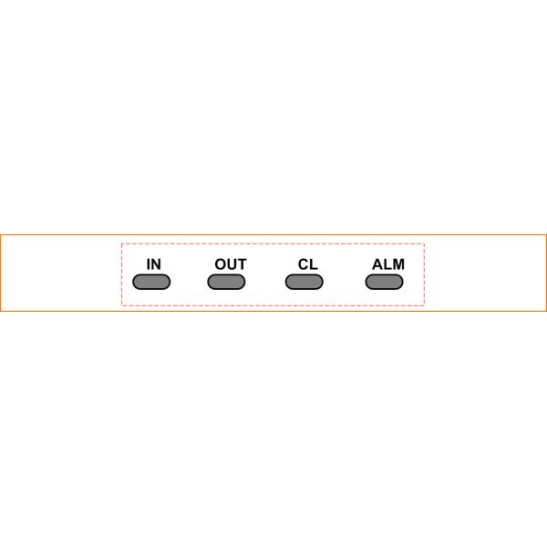
Rectifier Appearance
For the appearance of a ZXD1500 (V4.0) rectifier, see Figure 2-5.

1. Indicators
2. Grille
3. Handle
4. Stop pin
5. Input/output integrated socket
| Indicator Label | Status and Color | Meaning |
| IN(Input ) | Lit (green) | AC input power is normal. |
| OUT(Output) | Lit (green) | DC output power is normal. |
| CL(Current limit) | Lit (yellow) | Output current of the rectifier has reached its limit. |
| ALM(Alarm) | Lit (red) | An alarm has occurred. |
Centralized Supervision Unit
The Centralized Supervision Unit (CSU) manages the power
distribution unit, rectifiers and batteries of the ZXDU58 W121
system.
Functions
Collects the operational data and monitors the operation of the
system.
Provides alarm and necessary protection if the system is operating
abnormally.
Sends data to the background Supervision Center (SC) and receives
the commands from the SC. In this way, the system can be monitored
remotely.

1. Liquid Crystal Display (LCD)
2. Screen
3. Indicators
4. Reset button
5. Buttons
6. Handle
7. Power switch
8. Fastening screw
9. (Rear) Interface
Indicators
The indicators indicate the current operational status of the CSU.
For a description of the CSU indicators.
| Indicator Label | Status and Color | Meaning |
| PWR Power | Lit (green) | Power is applied to the CSU. |
| RUN Run | Flashing (green) | CSU is operating normally. |
| EQU Charge equalization | Lit (green) | Battery equalized charge is in-process. |
| COMM Communication | Flashing (yellow) | CSU is communicating with the connected PC. |
| ALM Alarm | Flashing (red) | An alarm or fault has occurred. |
Buttons
The reset button is used to restart the CSU.
Users can perform querying and setting operations through the
buttons laid on the front panel of the CSU.
For the function description of the buttons
| Indicator Label | Status and Color |
| ▲ | Turns pages (or items) upwards / increases values |
| ▼ | Turns pages (or items) downwards / decreases values |
| Esc | Exits and returns to the upper-level interface |
| Indicator Label | Status and Color |
| Enter | Confirms the current menu items/saves the current parameter setting/enters the lower-lever interface |
| ▲ + Enter | Displays help information |

|
